
Cell Phone Detector Circuit
The most common electronic equipment used now-a-days is Cell Phone or Mobile Phone. With advancement in communication technology, the requirement of cell phones has increased dramatically. A cell phone typically transmits and receives signals in the frequency range of 0.9 to 3GHz. This article provides a simple circuit to detect the presence of an activated cell phone by detecting these signals.
I have designed two circuits that act as Cell Phone Detector Circuit, one using a combination of Schottky Diode and a Voltage Comparator and the other using a BiCMOS Op-Amp.
Basic Principle of Mobile Phone Detector Circuit
The basic principle behind the Cell Phone Detector circuits is to detect the RF Signals. In the Schottky diode circuit, the Schottky Diode is used to detect the cell phone signal as they have a unique property of being able to rectify low frequency signals, with low noise rate. When an inductor is placed near the RF signal source, it receives the signal through mutual induction. This signal is rectified by the Schottky diode. This low power signal can be amplified and used to power any indicator like an LED in this case.
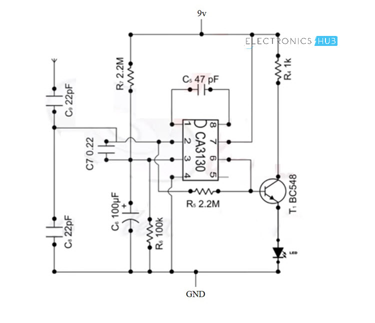
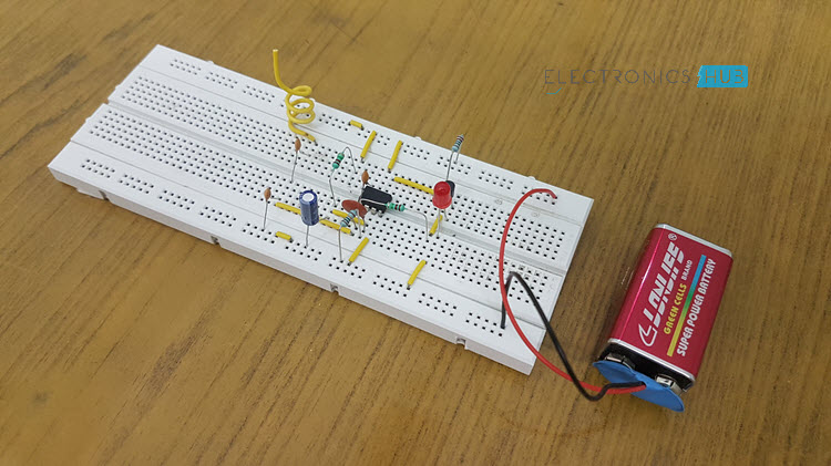
Circuit 1: Simple Cell Phone Detector Circuit
The first circuit of the cell phone detector is a simple implementation using an Op-amp and a few other passive components.
Components Required
- CA3130 Op-Amp
- Resistors – 2.2MΩ x 2, 100KΩ, 1KΩ
- Capacitors – 22pF x 2, 0.22nF, 47pF, 100µF
- BC548 NPN Transistor
- LED
- Antenna
- Connecting Wires
- Breadboard
- 9V Battery
Working
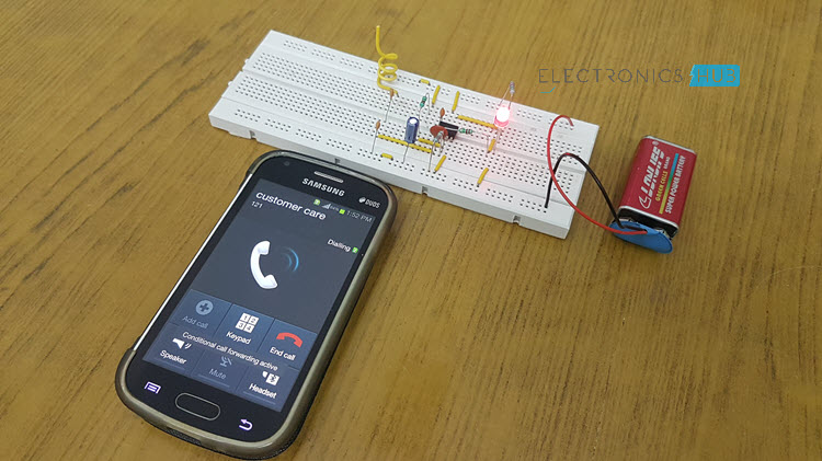
The Op-amp part of the circuit acts as the RF Signal Detector while Transistor part of the circuit act as the indicator. The capacitors collection along with the antenna are used to detect RF Signals when a cell phone makes (or receives) a phone call or sends (or receives) a text message.
Op-Amp reads the signals by converting the rise in current at input to voltage at output and the LED will be activated.
Circuit 2: Cell Phone Detector using Schottky Diode
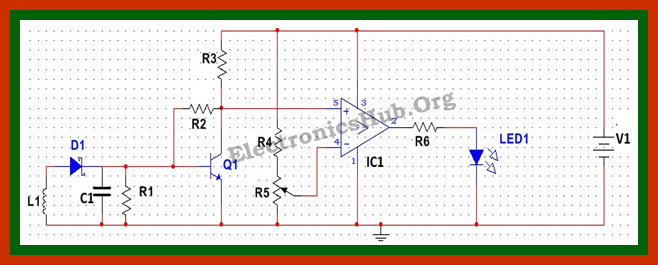
Circuit Diagram of Cell Phone Phone Detector – ElectronicsHub.Org
- V1 = 12V
- L1 = 10uH
- R1 = 100Ohms
- C1 = 100nF
- R2 = 100K
- R3 = 3K
- Q1 = BC547
- R4 = 200 Ohms
- R5 = 100 Ohms
- IC1= LM339
- R6 = 10 Ohms
- LED = Blue LED
Cell Phone Detector Circuit Design
Detector Circuit Design
The detector circuit consists of an inductor, diode, a capacitor and a resistor. Here an inductor value of 10uH is chosen. A Schottky diode BAT54 is chosen as the detector diode, which can rectify low frequency AC signal. The filter capacitor chosen in a 100nF ceramic capacitor, used to filter out AC ripples. A load resistor of 100 Ohms is used.
Amplifier Circuit Design
Here a simple BJT BC547 is used in common emitter mode. Since the output signal is of low value, the emitter resistor is not required in this case. The collector resistor value is determined by the value of battery voltage, collector emitter voltage and collector current.
Now the battery voltage is chosen to be 12 V (since maximum open source collector emitter voltage for BC 547 is 45V), operating point collector emitter voltage is 5 V and collector current is 2 mA. This gives a collector resistor of approx 3 K. Thus a 3 K resistor is used as Rc. The input resistor is used to provide bias to the transistor and should be of larger value, so as to prevent the flow of maximum current. Here we chose a resistor value of 100 K.
Comparator circuit Design
Here LM339 is used as comparator. The reference voltage is set at the inverting terminal using a potential divider arrangement. Since output voltage from the amplifier is quite low, the reference voltage is set low of the order of 4V. This is achieved by selecting a resistor of 200 Ohms and a potentiometer of 330 Ohms. An output resistor of value 10 Ohms is used as a current limiting resistor.
Mobile Phone Tracking Circuit Operation
In normal condition, when there is no RF signal, the voltage across the diode will be negligible. Even though this voltage is amplified by the transistor amplifier, yet the output voltage is less than the reference voltage, which is applied to the inverting terminal of the comparator. Since the voltage at non inverting terminal of the OPAMP is less than the voltage at the inverting terminal, the output of the OPAMP is low logic signal.
Now when a mobile phone is present near the signal, a voltage is induced in the choke and the signal is demodulated by the diode. This input voltage is amplified by the common emitter transistor. The output voltage is such that it is more than the reference output voltage. The output of the OPAMP is thus a logic high signal and the LED starts glowing, to indicate the presence of a mobile phone. The circuit has to be placed centimeters away from the object to be detected.
Theory Behind Cell Phone Tracking System
Mobile Phone Signal Detection using Schottky Diode
The signal from mobile phone is a RF signal. When a mobile phone is present near the circuit, the RF signal from the mobile induces a voltage in the inductor via mutual induction. This AC signal of high frequency of the order of GHz is rectified by the Schottky diode. The output signal is filtered by the capacitor.
Schottky diodes are special diodes formed by combining N type semiconductor material with a metal and are typically low noise diodes, operating at a high frequency. These diodes have a unique property of conducting at a very low forward voltage between 0.15 to 0.45V. This enables the diode to provide high switching speed and better system efficiency. The low noise is due to the very low reverse recovery time of about 100 per sec.
Signal Amplifier using BJT
BJT or bipolar junction transistor in its common emitter form is the most common amplifier used. A transistor amplifier works on the fact that the input base current is amplified to the output collector current by a factor of β. Here the emitter is the common terminal.
The circuit is biased using a voltage divider circuit formed by combination of two resistors. When a transistor is biased in active region, i.e. the emitter base junction is forward biased and the collector base junction is reverse biased, a small base current results in a larger collector current.
LM339 as Comparator
LM339 is a comparator IC containing 4 comparators. Here we are using only one comparator. When the voltage at non inverting (+) terminal is higher than the voltage at inverting terminal, the output voltage goes high. When the voltage at inverting terminal is higher, the output voltage goes low.
Cell Phone Detector Circuit Applications
- This circuit can be used at examination halls, meetings to detect presence of mobile phones and prevent the use of cell phones.
- It can be used for detecting mobile phones used for spying and unauthorized transmission of audio and video.
- It can be used to detect stolen mobile phones.
Limitations of Mobile Phone Detector Circuit
- It is a low range detector, of the order of centimetres.
- The Schottky diode with higher barrier height is less sensitive to small signals.